| Above-Ground Meter Pre-Locates UG Faults | 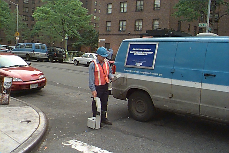 |
| Above-Ground Meter Pre-Locates UG Faults | |
The meter reduces the manhole openings required and reduces fault pre-locating time.
Year after year, the industry’s leading independent survey shows that Consolidated Edison of New York, Inc. (Con Edison) has the most reliable urban electric system in the nation. The fundamental design of the network system permits outages of key components while maintaining full service to customers, even on the most heavily loaded days. However, the same network architecture responsible for excellent reliability presents difficulty in fault locating due to its inherent design. The complex topology of each feeder, requires difficult and time consuming operations to localize underground faults, thereby directly affecting Con Edison’s competitive edge. This fact, coupled with the significant number of faults realized per year, was identified and scrutinized by a team of Con Edison operators, engineers and analysts. The analysis led to the development project of the "Real-time Meter for Fault Monitoring" (RMFM). The RMFM, commonly known to field crews as the "X27", significantly reduces the time to locate and repair underground network feeder faults by pre-locating faults from "above ground", entering manholes only for pinpointing.
Con Edison’s Electrical System is Large
The Con Edison distribution system covers 604 square miles and serves a population of over 8 million people. The service area includes the five boroughs (except for a small portion of Queens) of New York City and most of Westchester County. The electric distribution system consists of 55 area substations supplying 74 secondary networks and radial 33 kV, 27 kV, 13 kV and 4 kV load. As of January 1, 1998 the Company served 3,001,870 electric customers: 2,222,127 network and 797,645 radial. Approximately 86 percent of 23,048,813 kVA distribution transformer capacity is underground and 14 percent is overhead. The Con Edison system peak reached a record high of 11,013 MW on July 15, 1997.
Within the Con Edison electrical system there are 2,069 distribution feeders including twenty-four 33 kV, three hundred and ten 27kV, nine hundred and seventy 13 kV and seven hundred and sixty five 4 kV feeders which supply radial and network load. The underground 33 kV, 27kV, 13kV, and 4kV distribution system includes 252,336 manholes and boxes, 22,147 conduit miles of duct, and 31,971 underground transformers totaling 19,904,982 kVA and 86,858 miles of underground cable including primary, secondary and services. The overhead system which is comprised of 33kV, 27kV, 13kV, and 4kV lines includes 199,521 poles and 44,832 overhead transformers totaling 3,143,813 kVA and 32,336 miles of overhead wires including primary, secondary and services.
The Con Edison underground network consists of feeders with many branches and transformers. An average feeder may contain between 20 and 50 transformers (generally three phase 500 kVA and 1000 kVA units) that cannot be disconnected from the primary cable. The sections of cable are generally made up of different cable types with different insulating materials.
Fault Locating Methodology
The Con Edison system typically experiences about 2,000 faults (including test failures) annually. When a fault occurs on a primary cable or transformer, the substation circuit breaker automatically opens to remove the substation source. Soon after, the network protector opens to remove the low voltage source of backfeed, isolating the cable. Crews must then quickly work to locate and repair the fault so the feeder can be returned to service before the stress on the system leads to additional failures and potential outages.
For many years, Con Edison has used a feeder fault location method known as "thumping" which involves the application of high voltage pulses to the feeder. In thumping, the fault is first "conditioned" to reduce its resistance. Then, high voltage pulses are applied at the substation, using either a Thyratron or Capacitive Discharge (CD) test set. Field operators then travel the route of the feeder, entering manholes to take readings with a galvanometer that detects the pulse. If the pulse is present, the operator proceeds to the next manhole. The absence of a pulse indicates that the fault is located somewhere between the current manhole and the one previously checked. Although inherently time-consuming and labor intensive, when compared with other fault location methods, thumping has proven best-suited to the characteristics of Con Edison’s system. Other technology such as high voltage Time-domain-reflectometry (TDR) has been examined on network systems and has proved to be ineffective. The significant number of connections to the feeder from Y’s, Tee’s, splices, and transformers, along with the bonding of dissimilar cable types with varying propagation velocities, create indistinguishable reflections to an operator masking the identity of the fault. Even without multiple reflections, the TDR would not provide information as to which of the numerous branches contains the fault.
Committed to improving the localization and repair process of feeder faults, Con Edison contracted with AT&T - Bell Laboratories to develop the RMFM/X27 to pre-locate feeder faults from "above ground", opening manholes only to pinpoint the fault (figure right). Bell Laboratories and subcontractors, who specialized in the field of digital signal processing, conducted extensive research and development activities with the support of Manhattan Distribution Operations, Distribution Engineering and the Research and Development departments to develop the RMFM/X27. Bell Labs first delivered four prototypes in 1994 and the units operated flawlessly. Within a year, ruggedized units were in production and Con Edison purchased over 50 units from Lucent Technologies (formally AT&T) which were provided to distribution operating crews. As a result of Lucent Technologies decision to discontinue their involvement in the utility sector, Con Edison has continued with subcontractor Technology Enhancement Corporation (TEC) licensing further development of the RMFM/X27 technology into an externally marketable product call the "X35". The X35, developed by TEC, is in the prototype stage and makes use of today’s current advanced digital technology to reduce the size, weight, power, and cost of the RMFM/X27 without sacrificing performance (figure left).
The RMFM/X27 offers significant advantages over traditional fault locating equipment to support the increased demand for quickly identifying feeder faults. Since the RMFM/X27 operates totally from above ground, it has been shown to substantially reduce the time to find a fault. This time savings directly results from the notable reduction in manhole openings. The time saving is further realized when manholes require pumping or when parked cars block entry into the underground structure. Minimizing the time to find the fault directly translates into cost savings, as well as, helping to decrease the risk of customer outage.
The RMFM/X27 also supports the increasingly stringent environmental requirements that demand additional time and cost to pump and contain manhole water which may contain environmental contaminants. Since the RMFM/X27 operates from above ground, and since the unit can detect the thumper signal even through flooded manholes, pumping and containing efforts are drastically reduced. Reducing the fault locating time also reduces the time that a feeder is subjected to the high voltage test set pulses.. The meter supports the use of Kenotron surges to pre-locate a fault bypassing the conditioning effort. However, additional time is required to locate the fault in this mode.
How the RMFM/X27 is used
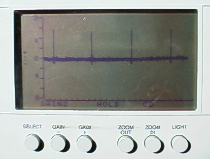
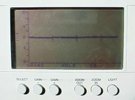
The RMFM/X27 is used above ground to display either polarized thumper signals or DC high voltage test set (Thyratron) signals to help direct field operators to the fault location. The electric field produced by the thumper discharge is detected and analyzed using state of the art digital signal processing techniques. This digital processing technique removes all non-related background electrical interference to produce a "picture" of the pulse on a high resolution Liquid Crystal Display, providing both amplitude and the direction of the fault. The amplitude and directional information is especially important when the field operators encounter a "Tee" or "Y" in the feeder. The information would indicate to an operator the branch which contains the fault.
With the thumper or Thyratron signal applied to the feeder, field operators would generally first position themselves over the feeder in the vicinity of the substation or "source" of the test signal. The RMFM/X27 would then be turned on and placed above ground over the feeder. With the meter in the appropriate mode (thumper or Thyratron), the field operator would take a measurement of the signal at this location to provide a "reference level" of the test set signal. The level of the pulse indicated on the display will be dependent upon the output level of the thumper equipment and the depth of the cable. Deeply buried cables or low output thumper equipment will produce small amplitude readings, while large thumper test sets or shallow buried cables will produce higher readings. The actual level at this point is not critical, but rather a reference for future readings made elsewhere on the cable.
After determining a baseline reference reading, the field operator would reference the feeder map and select the first substantial branch as a starting point. Once at that location, the operator would again position the RMFM/X27 directly over the feeder prior to the branch with its source indicator pointed parallel to the feeder toward the substation. Again, a measurement would be made and compared with the reference level obtained in the vicinity of the substation. A positive reading with an amplitude similar to the one taken in the vicinity of the substation indicates that the operator has not yet reached or passed the fault location (figure right). A small or negative reading would indicate that the operator has passed the fault or has chosen the wrong feeder leg (figure left). Assuming the operator has not passed the fault, he would proceed to take the same measurements on each leg of the branch. The branch that displays the most positive reading would indicate to the field operator the branch which contains the fault. The same branch selection strategy would then be followed to select the next test location. The operator would then continue with the same process until a section of cable is found which indicates a positive signal at its entry point and a small or negative signal at its exit point. These results would signify the faulted cable segment and field operators would then pull manholes to pinpoint the fault.
The RMFM/X27 has a number of additional features to help pre-locate a fault. However, simplicity in operation is maintained to provide an instrument which requires little training. In addition, the traditional fault locating methodology in which crews were educated is preserved, however implemented "above ground".
To facilitate comparisons in readings, the meter provides a "hold" function that freezes the display and permits an operator to travel to another location and take measurements. The RMFM/X27 also provides a "Zoom" capability that permits the display of both large and small signals to support the wide dynamic range due to varying depths of feeder cable. When cables are deeply buried, a "Gain" button can be pressed to increase the sensitivity of the meter. Conversely, the gain can be decreased for shallow depth cables. A single selector switch instructs the meter to search for either thumper signals or thyratron signals. The large Liquid Crystal Display (LCD) has excellent properties to facilitate both day and night viewing. The transflective display technology permits viewing in direct sunlight and also the darkest environments with the backlight turned "on". The display also supports a wide temperature range to permit operation in cold environments.
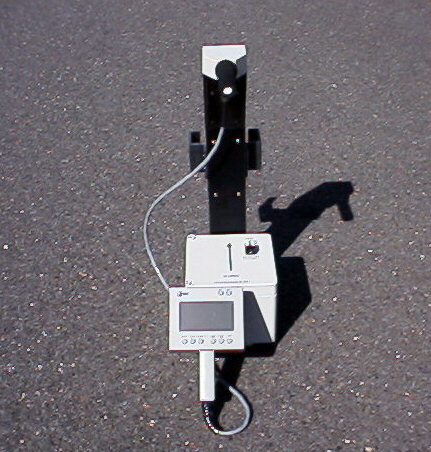
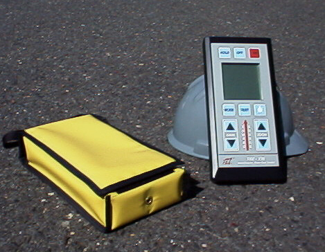
The RMFM/X27 consists of a base unit and a hand-held unit connected by a rugged cable and connector. The base enclosure houses the sensing coil, alkaline battery pack, and battery test circuitry. A holster is provided on the unit to hold the hand held unit when not in use or being transported. Constructed from a high strength compression molded fiberglass material, the NEMA rated 4X base is a strong, rugged enclosure able to withstand harsh weather conditions. The pistol grip type hand held unit houses all the electronics, display, and weather protected switches. The switches are located conveniently around the LCD and positioned properly to allow operation while wearing gloves. The hand held enclosure supports service truck operation with an optional truck interface unit. The case is injection molded with a polycarbonate impact-modified blend to provide high impact strength.
Meter Performance is High
Since Con Edison typically experiences about 2,000 faults per year, good statistical information on the RMFM/X27 performance was gathered. Based on data from field operators, the RMFM/X27 successfully directed crews to the fault 95% of the time. During the same period, it was recorded that 2,363 fewer manholes ( in Manhattan alone) were opened and pumped which permitted crews to pre-locate the fault on average 3 times faster than traditional methods. This translated to substantial cost savings achieving the goal of enhancing Con Edison’s competitive edge and significantly improving network fault locating technology.
The meter is simple to use and field operators were easily trained to correctly interpret its readings. Although the RMFM/X27 can be used on most any network, it does rely on three key factors for optimal performance. First, the feeder fault is assumed to be "to ground". That is, the RMFM/X27 is not designed to locate "opens" or "breaks" in cables which cannot be broken down by a thumper. Secondly, the RMFM/X27 relies upon good feeder bonding and earth grounding throughout the length of the feeder. Without good earth grounding throughout the length of the feeders, the high voltage thumper pulse traveling to the fault will return on the lead sheath (ground) of the same cable creating an equal and opposite field sufficient to cancel the thumper signal. Third, a thumper with good output capability is recommended. Thumpers that have very weak output power due to a small internal capacitor, are more difficult to detect above ground for deeply buried cables. A thumper with at least 12 microfarads of capacitance is recommended for best performance.
Future Developments
The development of the RMFM/X27 has proven successful in reducing the time to locate underground feeder faults and the time the feeder is subjected to high voltage discharges. However, Con Edison R&D is continuing to develop ways to virtually eliminate the pre-locate process. In a program conducted with the Electric Power Research Institute (EPRI), Con Edison with the support of TEC is testing a system installed on the Harlem Network in New York City that is capable of further reducing the time to locate faults. Field tests have been conducted using strategically placed sensor units with highly accurate clocks and synchronization, to determine the location of the fault from the actual breakdown itself. The system has the potential to virtually eliminate the application of high voltage pulses to pre-locate a fault.
Taken together, these two R&D projects promise the first significant advances in network feeder fault location in half a century.
Reprinted from "Transmission & Distribution World", June 1998